The first prototype was milled 2010-10-29 shortly after midnight and assembled later the same day by chrysn.
Everything worked better than expected.
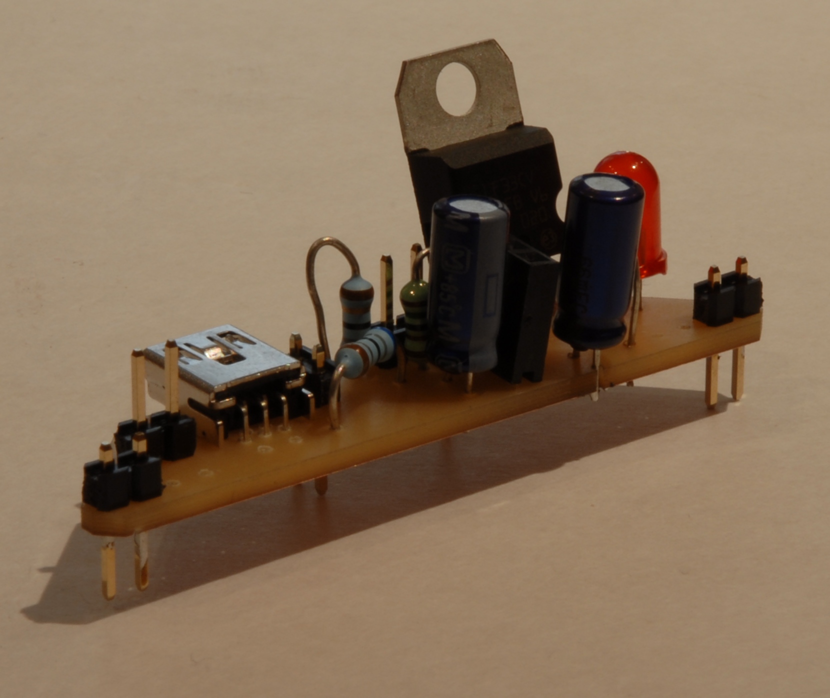
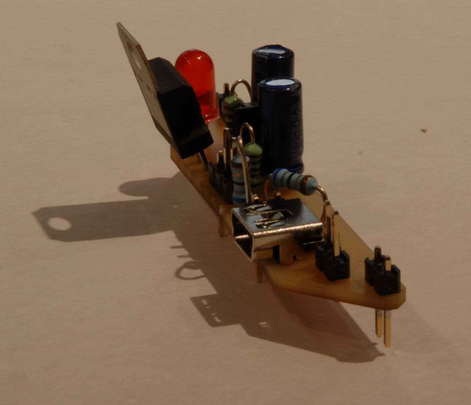
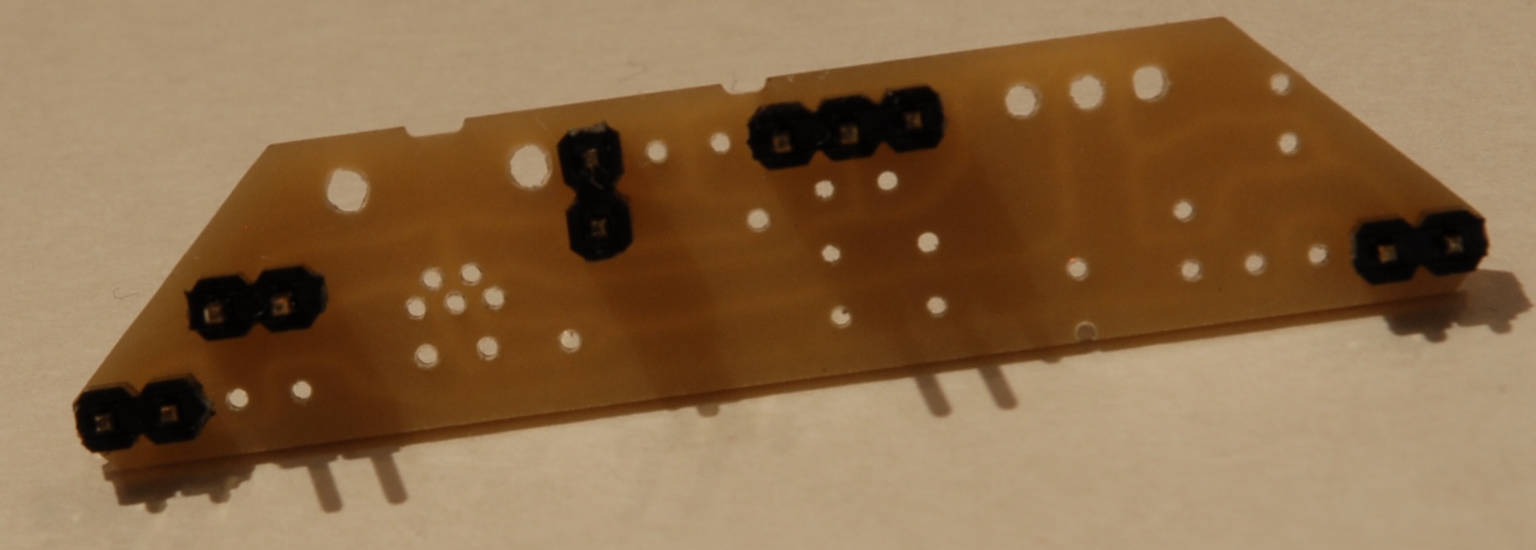
First parts to be assembled were the jumper pins, as they enable the whole thing to stand. It turned out that the easiest method to assemble the pullup board connector (BC4) and the pullup jumper (JP1) is to use a three-pin jumper part and pull the individual pins to the right positions. (Shoving the pins around is necessary anyway so the breadboard connectors protrude far enough.) This also gives better alignment for BC4.
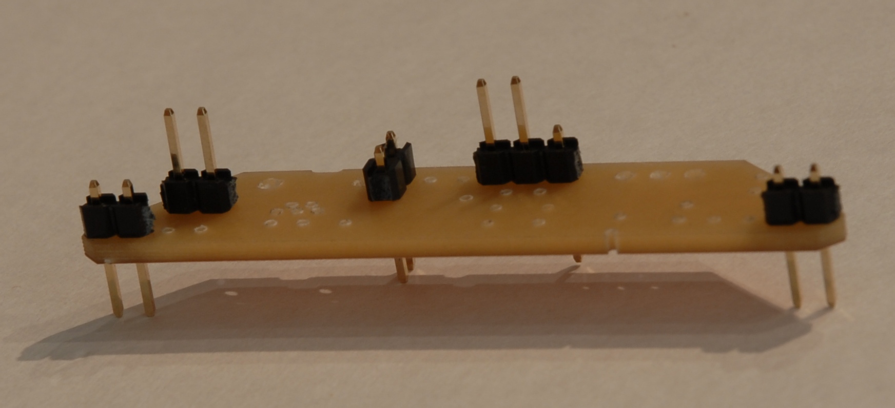
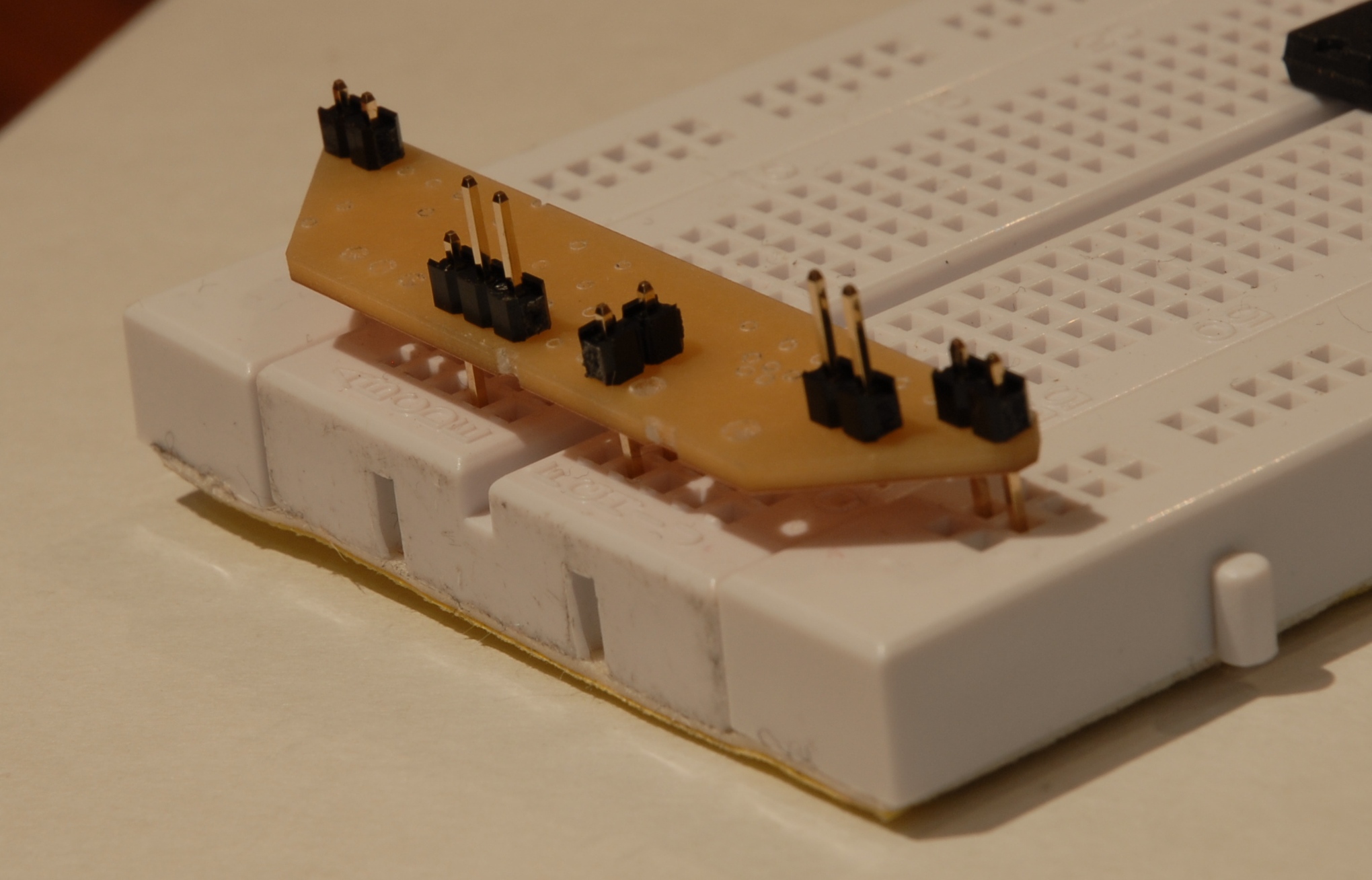
When putting the whole thing on the breadboard, the outer pins didn't fit exactly -- either the mill is calibrated badly or the breadboard power rails are too far out.
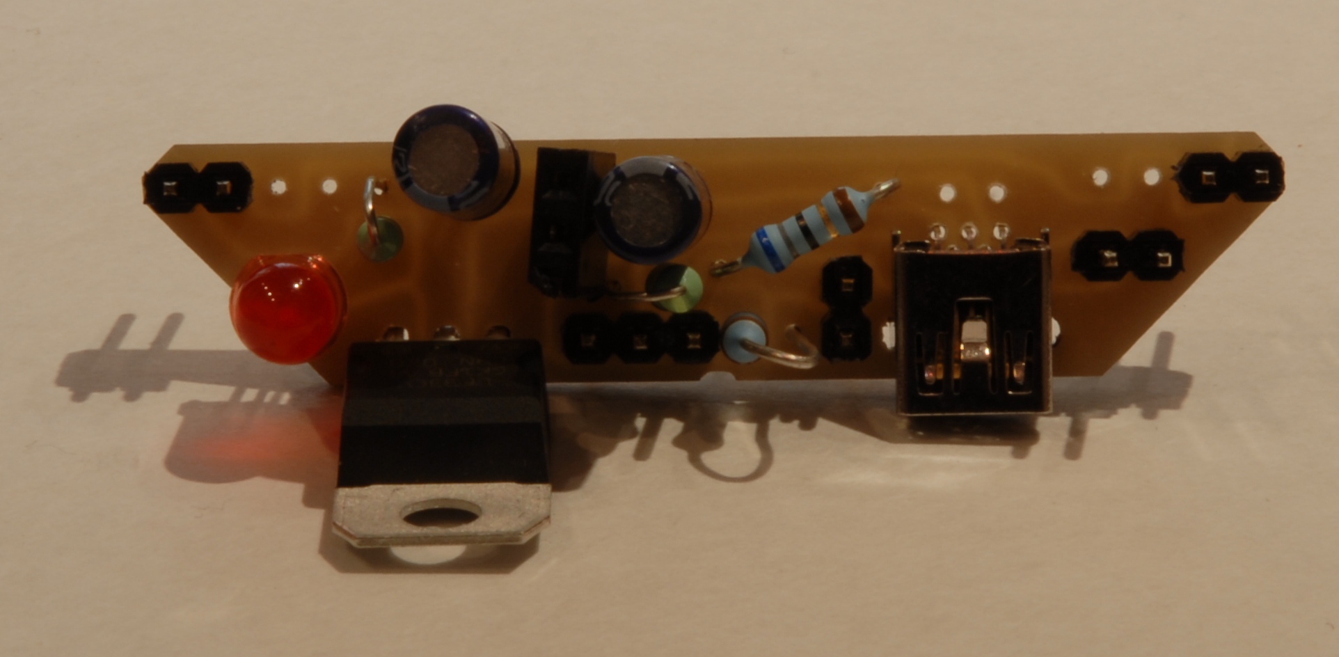
The assembly of the rest differs from the part list in that R4 was skipped (simply for lack of an appropriate resistor, and it works without as well), C1 and C2 are 10µF instead of 4.7µF (lack of parts and it works too), and R5 is 1kΩ instead of 100Ω (lack of parts, and it just makes the LED dimmer).
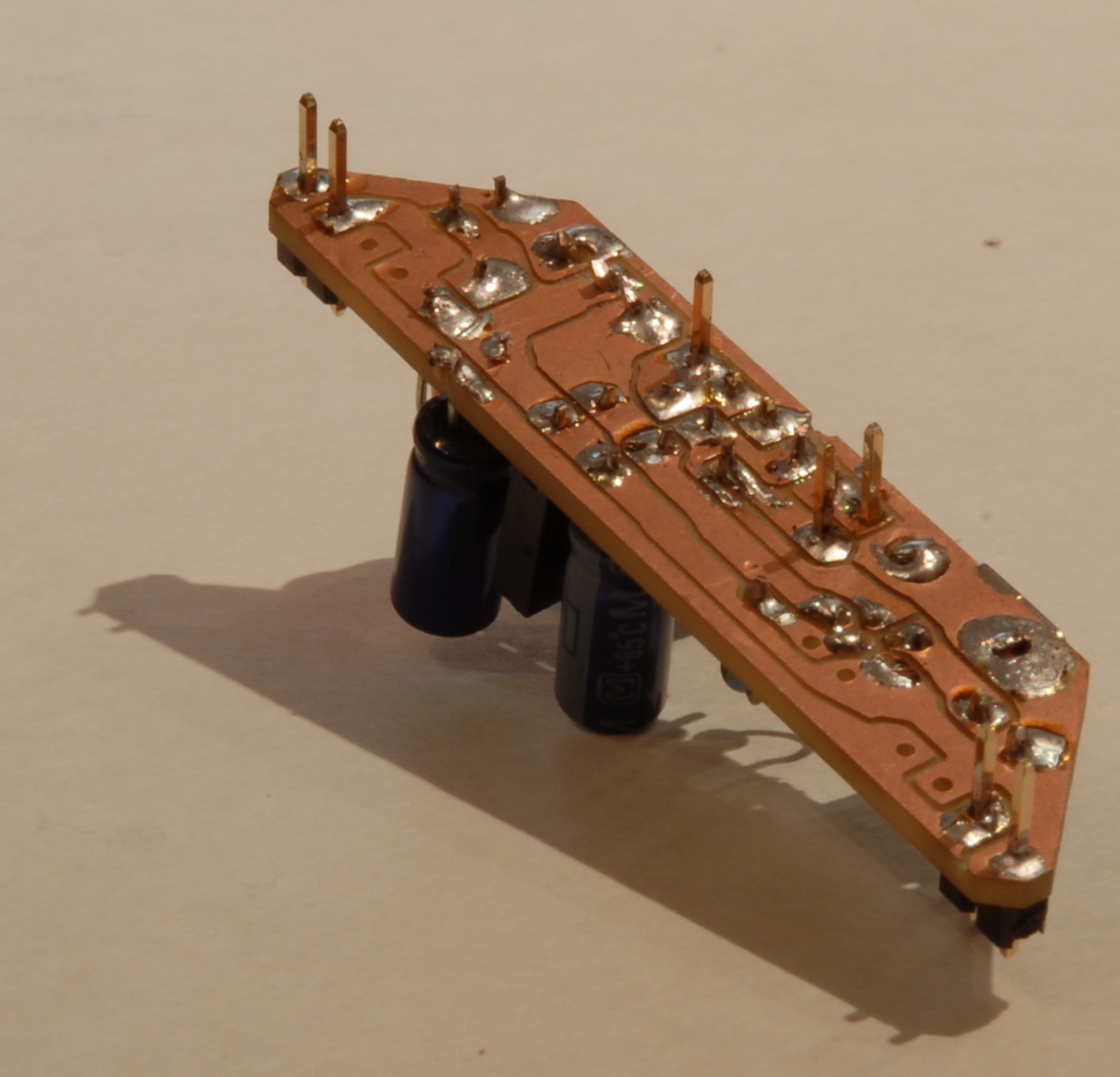
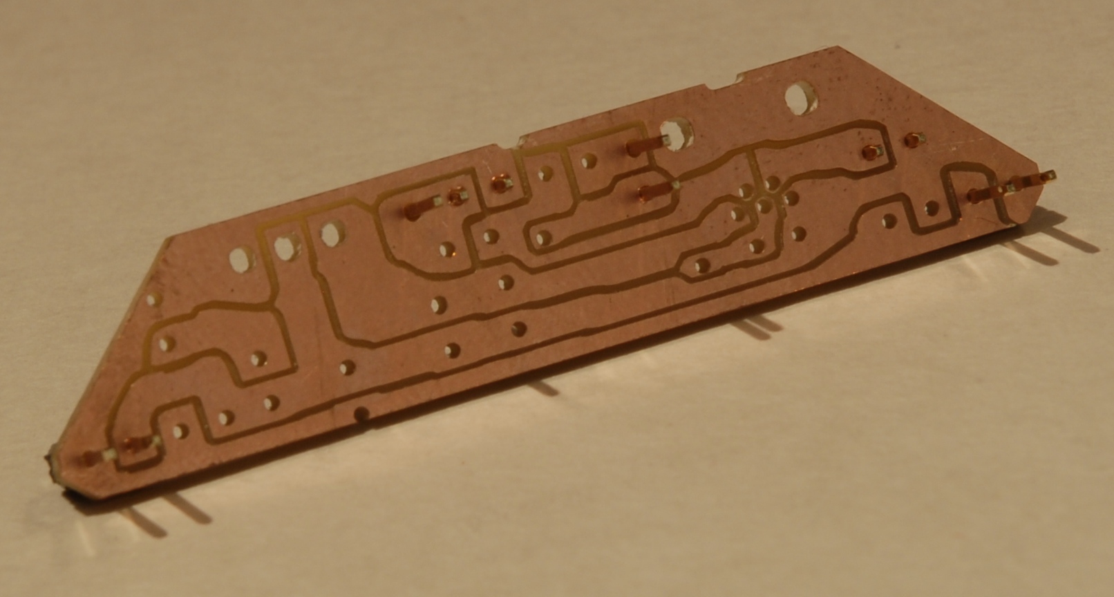
Soldering turned out to be quite easy, provided one is careful not to join adjacent traces (then, getting rid of the solder bridge is a mess; happened one time).
After soldering, everything turned out to work out of the box. The complete assembly depicts a usbBB connected to a ATMega168 with a 16MHz quartz and two jumpers for flashing and resetting, which were required as the first application tested was the USBaspLoader. It is connected to D- at pin 6 (D4) and D+ at pin 4 (D2/INT0). The pullup resistor is jumpered on the usbBB to be always on.